Or thrown to two other terminals pins 87a and 87. Ill note that if your relays have diodes in the coil circuit that diagram you posted wont work as drawn.
Starting the installation of your car security system.
You can find out more Diagram below
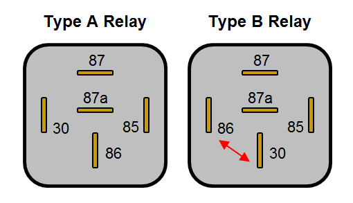
87a relay wiring diagram. Note that each pin is numbered. Relay with double output. Although most relays are labeled on the bottom for easy identification to the power.
Clarification on 87a terminal of relay i am installing a set of air horns on a truck and i would like to confirm a connection on the relay please. I am using a relay boxfuse box out of some kind of dodge productnot sure on what kind of vehicle because i got it. Numbers of a relay.
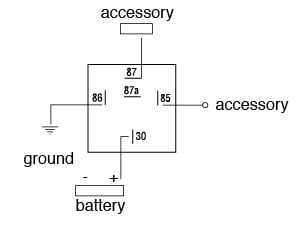
The instructions are not very detailed but the box does show a diagram which i. I have been looking at wiring diagrams for the past few hour while doing some wiring in my car and i was having some trouble findin the pin outs for a relay that i am going to use. To identify the 30 and 87a terminals apply 12v power to the 85 and 86 wires.
85 and 86 are the coil pins while 30 87 and 87a are the contact pins. This air horn set comes with two compressors driving one trumpet each. Looking at the diagram we see the pinout of a typical 12v relay.
Wiring diagram index 12v name description page name description page aa o power distribution 12 2 gd lighting forwardsignal cxugu7gu8 30. 30 85 87a 87 86 relay logic pink red black orange relay trigger 12v wire to a fused ignition source relay trigger ground wire to a good chassis ground to component basic relay wiring brake switch relay wiring pink red black. They follow guidlines setup by an electrical standards guidelines.
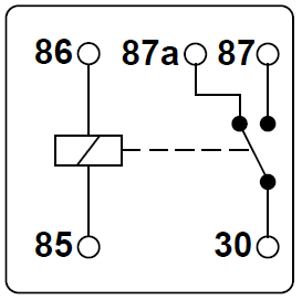
The spdt relay is one of the most useful configurations due to its flexibility it can be used as a. Two circuits terminals 87 and 87a have a common terminal 30. The relay should click coil pulled in and youll no longer have continuity between 30 and 87a.
When the relay is at rest 87a is connected to 30 and when the relay is energised 87 becomes connected to 30 but never both at the same time. If the coil is not activated 30 will always be connected to 87a. Thing about relays is that you can set 87 and 87a to be either open or closed depending on how you need the switch to work.
I cant remember the organization that standardized the numbers system specifically but essentially there is a guide that tells how the numbers are assigned based on funtion and timing when it was proposed and approved something like how the nfl uses certain sets of numbers for certain positions. Universal relay kit 500479 92965263 instruction sheet rev 60 9192013 this relay kit is designed for muli purpose use. If you want a closed relay you will want to wire to 87a.
If you want a normally open relay you will wire to 87. Terminal 87 is linked to pin number 87b giving double outputs from the single no contact. How to guides understanding relays.
87 and 87a are the two contacts to which 30 will connect.


0 comments:
Post a Comment